ICGOO在线商城 > 继电器 > 高频 (RF) 继电器 > G6K-2F-RF DC5

 Datasheet下载
- 型号: G6K-2F-RF DC5
- 制造商: Omron Electronics LLC
- 库位|库存: xxxx|xxxx
- 要求:
| 数量阶梯 | 香港交货 | 国内含税 |
| +xxxx | $xxxx | ¥xxxx |
查看当月历史价格
查看今年历史价格
G6K-2F-RF DC5产品简介:
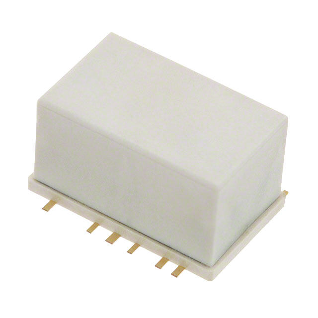
ICGOO电子元器件商城为您提供G6K-2F-RF DC5由Omron Electronics LLC设计生产,在icgoo商城现货销售,并且可以通过原厂、代理商等渠道进行代购。 G6K-2F-RF DC5价格参考¥66.09-¥104.41。Omron Electronics LLCG6K-2F-RF DC5封装/规格:高频 (RF) 继电器, 。您可以下载G6K-2F-RF DC5参考资料、Datasheet数据手册功能说明书,资料中有G6K-2F-RF DC5 详细功能的应用电路图电压和使用方法及教程。
Omron Electronics Inc-EMC Div生产的G6K-2F-RF DC5是一款高频(RF)继电器,其应用场景主要集中在需要对射频信号进行切换和控制的领域。以下是该型号继电器的主要应用场景:

1. 通信设备:
   该继电器适用于无线通信系统、基站设备、无线电收发器等场景,用于在不同射频通道之间切换或隔离信号。例如,在移动通信网络中,可以用于天线切换或信号路径选择。

2. 测试与测量设备:
   在射频测试仪器(如频谱分析仪、网络分析仪、信号发生器等)中,G6K-2F-RF DC5可用于切换不同的测试信号路径,以实现多路信号的高效测试。

3. 雷达与导航系统:
   雷达和导航设备需要高可靠性的射频信号切换,这款继电器能够满足这些系统的性能要求,确保信号传输的稳定性和准确性。

4. 医疗设备:
   在医疗成像设备(如超声波、MRI等)或其他需要射频信号处理的医疗仪器中,该继电器可用于信号路径的切换,以支持多种功能模式。

5. 卫星通信与广播:
   卫星地面站设备和广播电视系统中需要高频信号的切换,这款继电器可以用于天线切换、信号分配等关键环节。

6. 工业自动化:
   在工业环境中,涉及射频信号处理的自动化设备可能需要使用此类继电器来控制信号流向,提高系统的灵活性和效率。

7. 物联网(IoT)设备:
   在一些物联网应用中,高频继电器可用于射频模块的信号切换,支持设备在不同工作模式下的切换需求。

G6K-2F-RF DC5具有小型化设计、低插入损耗、高隔离度和长寿命的特点,非常适合上述高频应用场合。其DC5线圈电压版本为电路设计提供了更多的灵活性,能够适应各种电源条件下的使用需求。
| 参数 | 数值 |
| 产品目录 | |
| 描述 | RELAY RF DPDT 1A 5V |
| 产品分类 | |
| 品牌 | Omron Electronics Inc-EMC Div |
| 数据手册 | |
| 产品图片 |
|
| 产品型号 | G6K-2F-RF DC5 |
| rohs | 无铅 / 符合限制有害物质指令(RoHS)规范要求 |
| 产品系列 | G6K-RF |
| 产品培训模块 | http://www.digikey.cn/PTM/IndividualPTM.page?site=cn&lang=zhs&ptm=25458 |
| 产品目录绘图 |
|
| 产品目录页面 | |
| 关闭电压(最小值) | 0.5 VDC |
| 其它名称 | G6K 1211A |
| 其它有关文件 | |
| 包装 | 管件 |
| 安装类型 | 表面贴装 |
| 导通电压(最大值) | 4 VDC |
| 工作时间 | 3ms |
| 工作温度 | -40°C ~ 70°C |
| 开关电压 | 125VAC,60VDC - 最小值 |
| 标准包装 | 300 |
| 特性 | 1 GHz |
| 端子类型 | 鸥翼型 |
| 线圈功率 | 100 mW |
| 线圈电压 | 5VDC |
| 线圈电流 | 21.1mA |
| 线圈电阻 | 237 欧姆 |
| 线圈类型 | 无锁存 |
| 继电器类型 | RF |
| 触头外形 | DPDT(2 C 型) |
| 触头材料 | Silver(Ag),Gold(Au) |
| 释放时间 | 3ms |
| 额定接触(电流) | 1A |


- 商务部:美国ITC正式对集成电路等产品启动337调查
- 曝三星4nm工艺存在良率问题 高通将骁龙8 Gen1或转产台积电
- 太阳诱电将投资9.5亿元在常州建新厂生产MLCC 预计2023年完工
- 英特尔发布欧洲新工厂建设计划 深化IDM 2.0 战略
- 台积电先进制程称霸业界 有大客户加持明年业绩稳了
- 达到5530亿美元!SIA预计今年全球半导体销售额将创下新高
- 英特尔拟将自动驾驶子公司Mobileye上市 估值或超500亿美元
- 三星加码芯片和SET,合并消费电子和移动部门,撤换高东真等 CEO
- 三星电子宣布重大人事变动 还合并消费电子和移动部门
- 海关总署:前11个月进口集成电路产品价值2.52万亿元 增长14.8%
PDF Datasheet 数据手册内容提取
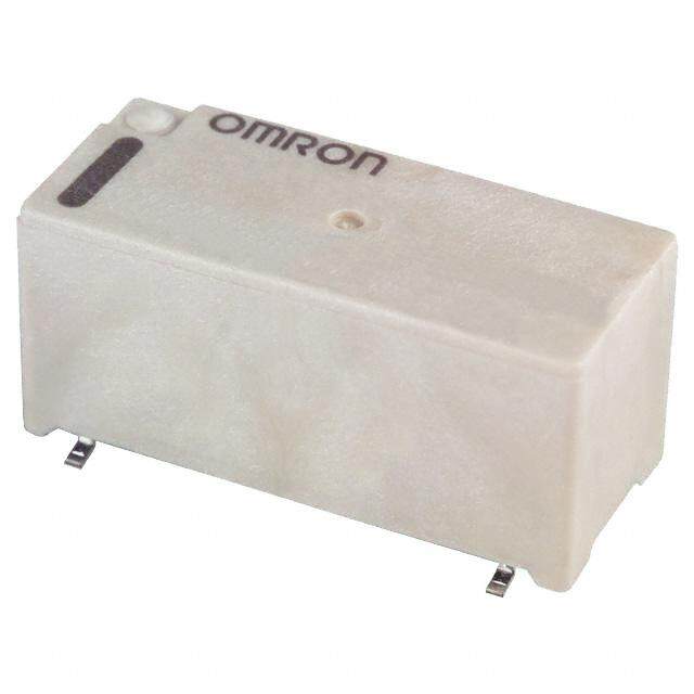
G6K(U)-2F(P)-RF(-S, -T) Surface-mounting High-frequency Relay Surface-mounting, 1-GHz-Band/ 3-GHz-Band, Miniature, DPDT, High-frequency Relay •Superior high-frequency characteristics (at 1 GHz), such as an isolation of 20 dB min. between contacts of the same polarity of 30 dB min. be- tween contacts of different polarity with an insertion loss of 0.2 dB max. •Miniaturized to 10.3 × 6.9 × 5.4 mm (L × W × H). •Rated power consumption of 100 mW with high sensitivity •Single-side stable and single-winding latching models are available. •Models with a smaller footprint (G6K(U)-2F-RF-S) are available to help save space. •G6K(U)-2F-RF-T models for 3-GHz band join the lineup with a downsized footprint. •New PCB terminals models are available. RoHS Compliant ■Model Number Legend ■Application Examples G6K@-@@-@-@ •Communications equipment G — — — — — 6 •Broadcasting and audio-visual equipment 1 2 3 4 5 K •Test & measurement equipment ( 1. Relay Function 4. Special Function U None: Single-side stable RF: High-frequency compatible )- 2 U: Single-winding latching 5. Terminal Shape F ( 2. Number of poles/ None: Standard P Contact Form S: Small footprint )-R 2: 2-pole/ DPDT (2c) T: Compatible with 3 GHz F 3. Terminal Shape (-S, F: Outside-L surface mount- - T ing terminals ) P: PCB terminals ■Ordering Information ●Standard Models with Surface-mounting Terminals Standard Specifications Relay Function Enclosure rating Contact form Model Rated coil voltage Minimum packing unit Single-side stable DPDT G6K-2F-RF 3, 4.5, 5, 12, 24 VDC 300 pcs/tray Fully sealed Single-winding latching (2c) G6KU-2F-RF 3, 4.5, 5, 12, 24 VDC 300 pcs/reel Board space-saving model Relay Function Enclosure rating Contact form Model Rated coil voltage Minimum packing unit Single-side stable DPDT G6K-2F-RF-S 3, 4.5, 5, 12, 24 VDC 300 pcs/tray Fully sealed Single-winding latching (2c) G6KU-2F-RF-S 3, 4.5, 5, 12, 24 VDC 300 pcs/reel Compatible with 3 GHz Relay Function Enclosure rating Contact form Model Rated coil voltage Minimum packing unit Single-side stable DPDT G6K-2F-RF-T 3, 4.5, 5, 12, 24 VDC 300 pcs/tray Fully sealed Single-winding latching (2c) G6KU-2F-RF-T 3, 4.5, 5, 12, 24 VDC 300 pcs/reel PCB terminals Relay Function Enclosure rating Contact form Model Rated coil voltage Minimum packing unit Single-side stable Fully sealed DPDT (2c) G6K-2P-RF 3, 4.5, 5, 12, 24 VDC 30 pcs/tube Note 1.When ordering, add the rated coil voltage to the model number. Example: G6K-2F-RF DC3 Rated coil voltage However, the notation of the coil voltage on the product case as well as on the packing will be marked as @@ VDC. Note 2.When ordering Relays in tape packing, add "-TR03" to the end of the model number. Example: G6K-2F-RF-TR03 DC3 Relays per reel: 300 pcs for -TR03 Be sure since "-TR" is not part of the relay model number, it is not marked on the relay case. When ordering tape packing, minimum order unit is 1 reel (300 pcs ✕ 1 = 300 pcs). Note 3.Surface mounting terminal (SMT) standard models are shipped in moisture-proof package. PCB terminal standard types do not require moisture proof packaging and therefore shipped in non-moisture-proof package. 1
G6K(U)-2F(P)-RF(-S, -T) Surface-mounting High-frequency Relay ■Ratings ●Coil: Single-side Stable (G6K-2F(P)-RF(-S, -T)) Must operate voltage Must release voltage Maximum voltage Item Rated current Coil resistance Power consumption (V) (V) (V) (mA) () (mW) Rated voltage % of rated voltage 3 VDC 33.0 91 4.5 VDC 23.2 194 5 VDC 21.1 237 80% max. 10% min. 150% Approx. 100 12 VDC 9.1 1,315 24 VDC 4.6 5,220 ●Coil: Single-winding Latching Models (G6KU-2F-RF(-S, -T)) Must set voltage Must reset voltage Maximum voltage Item Rated current Coil resistance Power consumption (V) (V) (V) (mA) () (mW) Rated voltage % of rated voltage 3 VDC 33.0 91 4.5 VDC 23.2 194 5 VDC 21.1 237 75% max. 75% max. 150% Approx. 100 12 VDC 9.1 1,315 24 VDC 4.6 5,220 Note 1.The rated current and coil resistance are measured at a coil temperature of 23°C with a tolerance of ±10%. Note 2.The operating characteristics are measured at a coil temperature of 23°C. Note 3.The maximum voltage is the highest voltage that can be imposed on the Relay coil instantaneously. ●Contacts ●High-frequency Characteristics *1 Item Load Resistive load Model G6K(U)-2F(P)-RF(-S) G6K(U)-2F-RF-T G 125 VAC, 0.3 A Item Frequency 1GHz 1GHz 3GHz 6 Rated load 30 VDC, 1 A Between K 1 GHz, 1 W * contacts of 20 dB min. 20 dB min. 18 dB min. (U Rated carry current 1 A the same )- Max. switching voltage 125 VAC or 60 VDC Isolation polarity 2 Max. switching current 1A Between F contacts of * This value is for a V.SWR of 1.2 max. at the load. 30 dB min. 30 dB min. 25 dB min. ( different P polarity )-R Insertion loss 0.2 dB max. 0.2 dB max. 0.6 dB max. F V.SWR 1.2 max. 1.2 max. 1.4 max. (- Maximum carry power 3W *2 S, Maximum switching power 1W *2 -T Note 1.The impedance of the measurement system is 50 . ) Note 2.The above values are initial values. *1. Contact your OMRON representative if the Relay will be used in an application that requires high repeatability in high-frequency characteristics for the microload region. (Such applications include testing and measurement equipment and ATE applications.) *2. These values are for a V.SWR of 1.2 max. at the load. ■Characteristics Relay Function Single-side stable models Single-winding latching models Item Model G6K-2F(P)-RF(-S, -T) G6KU-2F-RF(-S, -T) Contact resistance *1 100 m max. Operating (set) time *2 3 ms max. (approx. 1.4 ms) 3 ms max. (approx. 1.2 ms) Release (reset) time *2 3 ms max. (approx. 1.3 ms) 3 ms max. (approx. 1.2 ms) Minimum set/reset pulse time --- 10 ms Insulation resistance *3 1,000 M min. (at 500 VDC) Between coil and 750 VAC, 50/60 Hz for 1 min contacts Between contacts of 750 VAC, 50/60 Hz for 1 min Dielectric different polarity strength Between contacts of the 750 VAC, 50/60 Hz for 1 min same polarity Between ground and 500 VAC, 50/60 Hz for 1 min coil/contacts Vibration Destruction 10 to 55 to 10 Hz, 2.5 mm single amplitude (5 mm double amplitude) and 55 to 500 Hz, 300 m/s2 resistance Malfunction 10 to 55 to 10 Hz, 1.65 mm single amplitude (3.3 mm double amplitude) and 55 to 500 Hz, 200 m/s2 Shock Destruction 1,000 m/s2 resistance Malfunction 750 m/s2 Mechanical 50,000,000 operations min. (at a switching frequency of 36,000 operations/hour) Durability Electrical 100,000 operations min. (at a switching frequency of 1,800 operations/hour) Ambient operating temperature -40°C to 70°C (with no icing or condensation) Ambient operating humidity 5% to 85% Weight Approx. 0.95 g Note.The above values are initial values. *1. The contact resistance was measured with 10 mA at 1 VDC with a voltage drop method. *2. Values in parentheses are actual values. *3. The insulation resistance was measured with a 500 VDC megohmmeter applied to the same parts as those used for checking the dielectric strength. 2
G6K(U)-2F(P)-RF(-S, -T) Surface-mounting High-frequency Relay ■Engineering Data G6K-2F-RF Agile HP 8753D Vector Network Analyzer 50Ω terminaltion HP8753D ●High-frequency Characteristics ●High-frequency Characteristics ●High-frequency Characteristics (Isolation) *1, *2 (Insertion Loss) *1, *2 (Return Loss, V.SWR) *1, *2 G6K-2F-RF G6K-2F-RF G6K-2F-RF Average value (initial) Average value (initial) Average value (initial) Isolation (dB)1230000 TNeusmt bseurb ojefc Rt:e Gla6yKs-: 21F0- RpFcs Insertion loss (dB)0.01 TNeusmt bseurb ojefc Rt:e Gla6yKs-: 21F0- RpFcs Return loss (dB)12000 TNeusmt bseurb ojefc Rt:e Gla6yKs-: 25F p-RcsF 111...876WRVS· 0.2 30 1.5 40 40 Return loss 1.4 50 0.3 50 1.3 60 70 0.4 60 V.SWR 1.2 80 70 1.1 G 900 0.5 1 1.5 2 2.5 3 0.50 0.5 1 1.5 2 2.5 3 800 0.5 1 1.5 2 2.5 31.0 K6 Frequency (GHz) Frequency (GHz) Frequency (GHz) (U G6K-2F-RF-S Average value (initial) G6K-2F-RF-S Average value (initial) G6K-2F-RF-S Average value (initial) )-2 Isolation (dB)1230000 TNeusmt bseurb ojefc Rt:e Gla6yKs-: 21F0- RpFcs-S Insertion loss (dB)0.01 TNeusmt bseurb ojefc Rt:e Gla6yKs-: 21F0- RpFcs-S Return loss (dB)12000 TNeusmt bseurb ojefc Rt:e Gla6yKs-: 25F p-RcsF-S 111...876WRVS· ()-RPFF 40 0.2 30 1.5 (-S, 40 1.4 -T 50 Return loss 0.3 ) 50 1.3 60 70 0.4 60 1.2 V.SWR 80 70 1.1 900 0.5 1 1.5 2 2.5 3 0.50 0.5 1 1.5 2 2.5 3 800 0.5 1 1.5 2 2.5 31.0 Frequency (GHz) Frequency (GHz) Frequency (GHz) G6K-2F-RF-T G6K-2F-RF-T G6K-2F-RF-T Average value (initial) Average value (initial) Average value (initial) Isolation (dB)3210000 TNeusmt bseurb ojefc Rt:e Gla6yKs-: 25F p-RcsF-T NN..OC.. Insertion loss (dB)00..02 TNeusmt bseurb ojefc Rt:e Gla6yKs-: 25F p-RcsF-T NN..OC.. Return loss (dB)21000 TNeusmt bseurb ojefc Rt:e Gla6yKs-: 25F p-RcsF-T NN..OC.. 222...624WRVS· 0.4 30 2.0 40 40 1.8 50 Return loss 0.6 50 1.6 60 V.SWR 60 1.4 70 0.8 80 70 1.2 90 1.0 80 1.0 0 1 2 3 4 5 6 0 1 2 3 4 5 6 0 1 2 3 4 5 6 Frequency (GHz) Frequency (GHz) Frequency (GHz) 3
G6K(U)-2F(P)-RF(-S, -T) Surface-mounting High-frequency Relay G6K-2P-RF G6K-2P-RF G6K-2P-RF Average value (initial) Average value (initial) Average value (initial) Isolation (dB)3210000 TNeusmt bseurb ojefc Rt:e Gla6yKs-: 25P p-RcsF NN..OC.. Insertion loss (dB)00..01 TNeusmt bseurb ojefc Rt:e Gla6yKs-: 25P p-RcsF NN..OC.. Return loss (dB)21000 TNeusmt bseurb ojefc Rt:e Gla6yKs-: 25P p-RcsF NN..OC.. 111...867WRVS· 0.2 30 Return loss 1.5 40 40 1.4 50 V.SWR 0.3 50 1.3 60 60 1.2 70 0.4 80 70 1.1 90 0.5 80 1.0 0 0.5 1 1.5 2 2.5 3 0 0.5 1 1.5 2 2.5 3 0 0.5 1 1.5 2 2.5 3 Frequency (GHz) Frequency (GHz) Frequency (GHz) Note.Refer to the G6K specifications for basic specifications not shown above. *1. Ambient temperature condition: 23°C *2. The high-frequency characteristics depend on the mounting board. Be sure to check operation including durability in actual equipment before use. ■Dimensions (Unit: mm) Standard Specifications Mounting Dimensions (Top View) TerminalArrangement/ Tolerance: ±0.1 mm InternalConnections G6K-2F-RF (TopView) G G6KU-2F-RF G6K-2F-RF 6 7.6 Orientation mark K 3.25 .4 ( 8 7 6 5 U 12.8 )- 10.3 0.5 − 2 F 0.6 6.9 1.8 7 + 2.5 ( 1 2 3 4 P 5.4 0.3 )-R 2.5 F 0.5 7.8 0.8 G6KU-2F-RF (-S, 1.35 3.25 .4 1.95 (1.35) Orientatio8n mar7k 6 5 - 7.6 11.5 T − + ) S R + − 1 2 3 4 Note 1.Each value has a tolerance of ±0.3 mm. Note 2.The coplanarity of the terminals is 0.15 mm max. Note: Check carefully the coil polarity of the Relay. Board space-saving model Mounting Dimensions (Top View) TerminalArrangement/ Tolerance: ±0.1 mm InternalConnections G6K-2F-RF-S 0.85 1.55 (TopView) G6KU-2F-RF-S 1.5 0.85 8.8 G6K-2F-RF-S 7.6 Orientation mark G6KV-2DFC-RF-S 7.8 8.6 1.2 3.25 .4 8 7 6 5 JAPAN 1.6 − + 10.7 10.3 7.5 2.1 1.8 7 1 2 3 4 0.6 6.9 5.4 0.3 (1.35) 0.8 G6KU-2F-RF-S Orientation mark 1 1.8 0.5 8 7 6 5 1.35 3.25 .4 − + S R 7.6 + − Note 1.Each value has a tolerance of ±0.3 mm. 1 2 3 4 Note 2.The coplanarity of the terminals is 0.15 mm max. Note: Check carefully the coil polarity of the Relay. 4
G6K(U)-2F(P)-RF(-S, -T) Surface-mounting High-frequency Relay Compatible with 3 GHz Mounting Dimensions (Top View) TerminalArrangement/ Tolerance: ±0.1 mm InternalConnections G6K-2F-RF-T 0.85 0.5 0.85 (TopView) G6KU-2F-RF-T G6K-2F-RF-T 7.6 Orientation mark 5.4 G6K1-22FV-DRCF -T G6KV-2DFC-RJAFP-TAN 7.8 8.6 4-1.15 1.1 3.2 1.35 8 − 7 6 5 2.2 2.2 + 4.8 1 2 3 4 10.7 10.3 10.8 7 1.1 6.9 4.8 G6KU-2F-RF-T Orientation mark 5.4 0.6 0.3 1.35 2.2 2.2 (2.45) 8 7 6 5 14-0.8 0.5 − + 1.35 3.2 PLaCyBe ri nSftorurmctuarteio: n2L S+ R− 5.4 Finished Thickness: 0.6 mm 7.6 Copper Thickness: 18 µm 1 2 3 4 Note 1.Each value has a tolerance of ±0.3 mm. Note 2.The coplanarity of the terminals is 0.15 mm max. Note 3.The board dimensions are the dimensions that were Note: Check carefully the coil polarity of the Relay. used to measure the high-frequency characteristics given in the engineering data. The high-frequency characteristics and soldering con- ditions will depend on the type of board that is actually used. Always confirm applicability with the actual equipment before you use the Relay. G 6 PCB terminals PCB Mounting Holes (Bottom View) TerminalArrangement/ K G6K-2P-RF Tolerance: ±0.1 mm Inter(nBaolttComonVnieecwt)ions (U )- 2 13.3 2.54 Twelve, 0.85-dia. holes Orientation mark F 10.4 6.9 ( P 2.54 1 2 3 4 )- 5.5 max. + R 5.08 F 3.4 0.3 00..54 − (-S, (0.89) 8 7 6 5 2.54 0.15 (0.3) 12.7 -T 5.08 5.08 ) 7.62 Note: Check carefully the coil polarity of the Relay. 10.16 12.7 Note.Each value has a tolerance of ±0.3 mm. 5
G6K(U)-2F(P)-RF(-S, -T) Surface-mounting High-frequency Relay ■Tube Packing and Tape Packing Specifications Surface mounting terminal (SMT) standard models are shipped in moisture-proof package, and PCB terminal standard types do not require moisture proof packaging and therefore shipped in non-moisture-proof package. Please refer to "Correct Use" for handling after opening moisture-proof packaging for Surface mounting terminal (SMT) models. (1)Tube Packing 3. Carrier Tape Dimensions •G6K-2P-RF in tube packing are arranged so that the G6K(U)-2F-RF orientation mark of each Relay in on the left side. Fifty Relays 12±1.0 5.9±0.1 are packed on one tube. 1.5+00.1 dia. 2±0.1 4±0.1 A B 11..7755±±00..11 0.4±0.1 Be sure not to make mistakes in Relay orientation when mounting the Relay to the PCB. 11.5±0.1 24±0.2 13.4±0.1 Stopper Orientation of Relays Stopper 10.9±0.1 (green) (gray) 3°−10°° B B-B Cross Section A 4.25±0.1 Tube length: 520 mm (stopper not included) 3°−10°° No. of Relays per tube: 30 pcs A-A Cross Section (2)Tape Packing (Surface Mounting Terminal Models) •Add “TR03” to the end of the model number to order Relays in 8.5±0.1 tape packing. G6K(U)-2F-RF-S(-T) If “-TR03” is not added, the Relays will be provided in tray 12±0.1 5.9±0.1 G6 packing. 1.5+00.1 dia. 2±0.1 4±0.1 A B 11..7755±±00..11 0.4±0.05 Relays per reel:300 pcs K (U Minimun ordering unit:1 reel (300 relays) 11.5±0.1 )- 24±0.3 11.3±0.1 2 1. Direction of Relay Insertion F ( 3° max. P B B-B Cross Section )- R A F T(coopv etarp teape) 3° max.9.2±0.1 (- S, A-A Cross Section - T ) Carrier tape Embossed tape Pulling Direction G6K(U)-2F-RF G6K(U)-2F-RF-S(-T) Orientation mark Orientation mark Pulling Pulling direction direction 2. Reel Dimensions 29.5±1 25.5±0.5 13±0.2 dia. 2±0.5 21±0.8 dia. A 330 80 R1 Enlarged View of Section A 6
G6K(U)-2F(P)-RF(-S, -T) Surface-mounting High-frequency Relay ■G6K(U)-2F-RF(-S, -T) Recommended Soldering Method ●Recommended Conditions for IRS Method (Surface-mounting Terminals) (1) IRS Method (Mounting Solder: Lead) •The thickness of cream solder to be applied should be between 200 and 250 m and the land pattern should be C) mperature (° •bdTaioas gmerdaa mionn,t a wOineM trhReecO ocNomr’smre recentc dso omaldpmeperlyinnindgge j dos ionPltCd seBhr opwwaitntht e itnrhn et.h seo flodlelorwinign g Te220~ Soldering conditions shown on the left. 245 Correct Soldering Incorrect Soldering 180~ 200 Relay Terminal Land Preheating 150 Heel fillet is PCB formed Solder Insufficient amount of solder Excessive amount of solder Check the soldering in the actual mounting conditions before use. 90~120 20~30 Time (s) (The temperature profile indicates the temperature on the circuit board sur- (2) IRS Method (Mounting Solder: Lead-free) C) mperature (° C25a5s°eC t ompa pxa.nel (peak): Te Soldering G 250 max. 6 230 K ( 180 U )- 2 F 150 Preheating (P )- Relay terminal R section F (- 120 max. 30 max. S, Time (s) - (The temperature profile indicates the temperature on the PCB.) T ) 7
G6K(U)-2F(P)-RF(-S, -T) Surface-mounting High-frequency Relay ■Safety Precautions ●For general precautions on PCB Relays, refer to the precautions provided in General Information of the Relay Product Data Book. Correct Use ●Relay Handling ●Coating •Use the Relay as soon as possible after opening the •Do not use silicone coating to coat the Relay when it is moistureproof package. (As a guideline, use the Relay within mounted to the PCB. Do not wash the PCB after the Relay is one week at 30°C or less and 60% RH or less.) If the Relay is mounted using detergent containing silicone. Otherwise, the left for a long time after opening the moisture-proof package, detergent may remain on the surface of the Relay. the appearance may suffer and seal failure may occur after the ●Repeatability solder mounting process. To store the Relay after opening the •Contact your OMRON representative if the Relay will be used moisture-proof package, place it into the original package and in an application that requires high repeatability in seal the package with adhesive tape. high-frequency characteristics for the microload region. (Such •When washing the product after soldering the Relay to a PCB, applications include testing and measurement equipment and use a water-based solvent or alcohol-based solvent and keep ATE applications.) the solvent temperature to less than 40°C. Do not put the Relay in a cold cleaning bath immediately after soldering. ●About use of an IC socket. ●Environmental Conditions for Usage, Storage, and For: G6K-2P-RF Transport •When using IC sockets, select IC sockets by confirming that •Avoid direct sunlight when using, storing, or transporting the the sockets Rated/Spec./Characteristics are within the range Relay and maintain normal temperature, humidity, and of using condition. pressure conditions. Also, confirm whether there is any problem of electric ●Long-term, Continuous ON Contacts capability or plug insertion or not with actual using condition. G •Using the Relay in a circuit where the Relay will be ON continuously ●Others 6 for long periods (rather than switching) can lead to unstable contacts For: G6K-2P-RF K because the heat generated by the coil itself will affect the insulation •The dotted line below on the surface of relay is connected with ( U and can cause a film to develop on the contact surfaces. We a metal case (ground). )- recommend using a latching relay (magnetic-holding relay) in this So confirm the actual influence of insulation and signal 2 F kind of circuit. If a single-side stable model must be used in this kind characteristics when designing. of circuit, we recommend adding fail-safe circuits in case the contact ( P fails or the coil burns out. The dotted line is connected )-R ●Claw Securing Force During Automatic Mounting 1 mm with a ground terminal. F •During automatic insertion of Relays, be sure to set the BOTTOM VIEW (-S, securing force of each claw to the following so that the Relay’s 1 mm characteristics will be maintained. A A’ - T ) C Ground terminal Metal case A B Direction A: 1.96 N max. Gap bettweeenr eala Py CbBo ttaonmd Direction B: 4.90 N max. 0.3 mm Surface of a PCB Direction C: 1.96 N max. A-A’ Cross Section Secure the claws to the shaded area. Do not attach them to the center of Metal case the Relay or just one part of the Relay. (cid:129) Application examples provided in this document are for reference only. In actual applications, confirm equipment functions and safety before using the product. (cid:129) Consult your OMRON representative before using the product under conditions which are not described in the manual or applying the product to nuclear control systems, railroad systems, aviation systems, vehicles, combustion systems, medical equipment, amusement machines, safety equipment, and other systems or equipment that may have a serious influence on lives and property if used improperly. Make sure that the ratings and performance characteristics of the product provide a margin of safety for the system or equipment, and be sure to provide the system or equipment with double safety mechanisms. Note: Do not use this document to operate the Unit. OMRON Corporation Electronic and Mechanical Components Company Contact: www.omron.com/ecb Cat. No. K242-E1-07 0118(0207)(O) 8